Back to Input Deck Cards
Back to GRID
UNSTRUCTURED
Defines a standard finite element format where cells (elements) are defined by lists of vertices and vertices are defined by coordinates. We often refer to these as implicit unstructured grids. See PFLOTRAN_cell_numbering_schemes.pdf for cell face and vertex numbering schemes.
ASCII File Format
The first line specifies the number of cells and vertices. Cells are then specified, one per line with a single character that defines cell type followed by a list of the cell’s vertices (see PFLOTRAN_cell_numbering_schemes.pdf for vertex numbering schemes.)
Vertices are specified, one per line after cells through a list of coordinates (in units of meters). Vertex IDs follow 1-based numbering.
NUM_CELLS: Number of cells in grid
NUM_VERTICES: Number of vertices in grid
CELL_TYPE
T = tetrahedron (4 vertices)
P = pyramid (5 vertices)
W = wedge (6 vertices)
H = hexahedron (8 vertices)
VERTEX_#: Vertex ID (1-based ordering)
VERTEX_X_COORDINATE: X coordinate of vertex [m]
NUM_CELLS NUM_VERTICES
CELL_TYPE VERTEX_1 VERTEX_2 ... VERTEX_N
...
CELL_TYPE VERTEX_1 VERTEX_2 ... VERTEX_N
VERTEX_X_COORDINATE VERTEX_Y_COORDINATE VERTEX_Z_COORDINATE
...
VERTEX_X_COORDINATE VERTEX_Y_COORDINATE VERTEX_Z_COORDINATE
Example
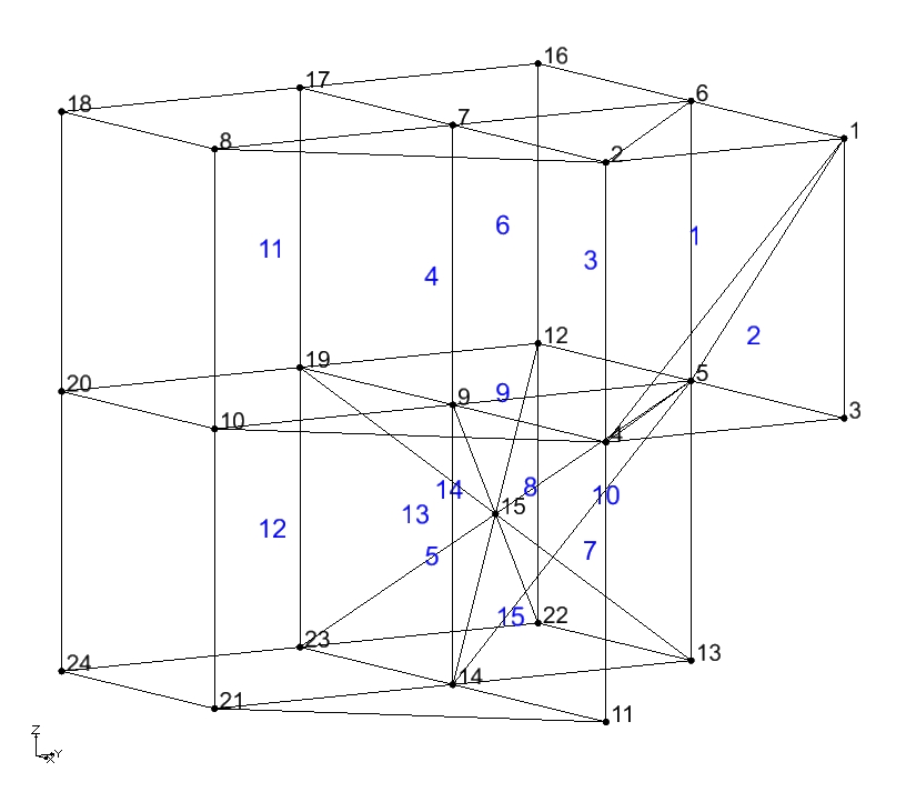
Example implicit unstructured grid in ASCII format (see mixed.ugi).
15 24
P 4 5 6 2 1
T 4 3 5 1
W 2 7 6 4 9 5
W 8 7 2 10 9 4
W 10 9 4 21 14 11
H 19 9 5 12 17 7 6 16
T 5 13 14 15
T 5 14 9 15
P 5 9 19 12 15
P 13 5 12 22 15
H 20 10 9 19 18 8 7 17
H 24 21 14 23 20 10 9 19
P 23 19 9 14 15
P 22 12 19 23 15
P 22 23 14 13 15
5.000000e+00 5.000000e+00 5.000000e+00
5.000000e+00 2.500000e+00 5.000000e+00
5.000000e+00 5.000000e+00 2.500000e+00
5.000000e+00 2.500000e+00 2.500000e+00
2.500000e+00 5.000000e+00 2.500000e+00
2.500000e+00 5.000000e+00 5.000000e+00
2.500000e+00 2.500000e+00 5.000000e+00
2.500000e+00 0.000000e+00 5.000000e+00
2.500000e+00 2.500000e+00 2.500000e+00
2.500000e+00 0.000000e+00 2.500000e+00
5.000000e+00 2.500000e+00 0.000000e+00
0.000000e+00 5.000000e+00 2.500000e+00
2.500000e+00 5.000000e+00 0.000000e+00
2.500000e+00 2.500000e+00 0.000000e+00
1.250000e+00 3.750000e+00 1.250000e+00
0.000000e+00 5.000000e+00 5.000000e+00
0.000000e+00 2.500000e+00 5.000000e+00
0.000000e+00 0.000000e+00 5.000000e+00
0.000000e+00 2.500000e+00 2.500000e+00
0.000000e+00 0.000000e+00 2.500000e+00
2.500000e+00 0.000000e+00 0.000000e+00
0.000000e+00 5.000000e+00 0.000000e+00
0.000000e+00 2.500000e+00 0.000000e+00
0.000000e+00 0.000000e+00 0.000000e+00
Image of the mixed.ugi. This is solely a small test grid from the regression tests. It does not reflect a realistic subsurface domain.

HDF5 File Format
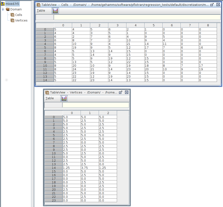
Two HDF5 datasets (Cells and Vertices) are placed within an named Domain within the HDF5 file. Cells defines the cell type and the cell’s vertices, while Vertices defines the vertex coordinates. As an example, consider the ASCII example above with 15 cells and 24 vertices.
Cells
Domain/Cells is a 2D integer (i4) dataset and sized 15x9 (number of cells X 9) [e.g. NumPy.zeros((15,9),dtype=’i4’)]. The second dimension of size 9 specifies the cell type in the first index and the cell vertex IDs in the remaining 8 indices, similar to the ASCII format above. The maximum number of vertices is 8. Thus, 1 + 8 = 9. (see PFLOTRAN_cell_numbering_schemes.pdf for vertex numbering schemes.)
Integer Cell Types:
4 = tetrahedron (4 vertices)
5 = pyramid (5 vertices)
6 = wedge (6 vertices)
8 = hexahedron (8 vertices)
Note that the remaining columns on each row in the HDF5 dataset are padded with zeros to preserve a rectangular dataset. Vertex IDs follow 1-based numbering.
Vertices
Domain/Vertices is a 2D double precision (f8) dataset and sized 24x3 (number of vertices X 3) [e.g. NumPy.zeros((24,3),dtype=’f8’)]. The first dimension is the number of vertices and the second dimension accommodates the (3) X, Y, and Z coordinates.
Example
Example implicit unstructured grid in HDF5 format (see mixed.h5). Note the zero-based numbering at the left side is HDFView’s numbering, not the cell ID.

